No strings attached!Dead Rail Prototype Project
I stumbled across the topic of radio controlled model trains, powered by onboard batteries several times in recent years. Especially within the 0-scale narrow gauge community there seems to be a growing interested in this kind of operation. As there are no ready to run train sets available at the time, “Dead Rail”- as the experts call it, is for tinkers who like to experiment. Well, that for sure triggered my curiosity and I started my own little Dead Rail project.
The idea behind Dead Rail
In order to get a better understanding about RC train control and battery powered operation let’s have quick view on “conventional” DCC. Digital Command Control is essentially a power-line system utilizing the rails as common carrier for power and digital control signals. Usually a command station generates the signal which in turn gets amplified by a booster therefore adding the power to move the locomotives. Each locomotive carries a so-called “decoder” that, on one hand side extracts the control information from the power line signal and on the other hand refurbishes the digitally chopped up power current into a more suitable format for the engines DC motors.
The Dead Rail approach follows the principles mentioned above but keeps the control signals separate from the source of power till to the last few inches. There are several RC control systems for model trains on the market and no standard regarding the transmission has been established yet. But basically all systems send some sort of radio signal to a receiver on the train which in turn converts the information and merges it with the power from onboard batteries to control the motor as well as auxiliaries. After some research I decided to give the Tam Valley Depot system a try. It features a sender module which puts up the DCC signal from the command station as well as small receiver boards that go between the batteries and the DCC decoder in the locomotive. The DCC signal is so to say “tunneled” over the air . Hence I can still use the already existing DCC throttles and even run Dead Rail locos on the same (powered) track as the “conventional DCC” ones should the need arise. I’d like to mention that Dead Rail is not a cheap affair as extra cost for batteries, sender/receiver modules etc. sum up to a significant investment. So, in the particular case, saving on new throttles is good news. Sure on the other hand, if one chooses to go 100% Dead Rail some savings will be achieved due to very limited (to none) layout wiring.
So far so good for the theory. Now let’s put that all together and have a look on my first Dead Rail installation project:
The Locomotive
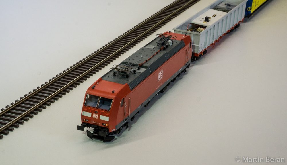
I started out with a H0 model of a Deutsche Bahn Class 185 electric engine made by Roco. The miniature version of this contemporary locoomotive provides a good base for such an undertaking as it is not too expensive and features a well engineered chassis modern Roco products are well known for.
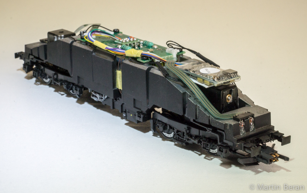
I had to alter the wiring only slightly in order to make the locomotive ready for Dead Rail operation. As the DCC signal will come form a separate power car, couplers with electrical connections got installed on the rear (cab #2) side. 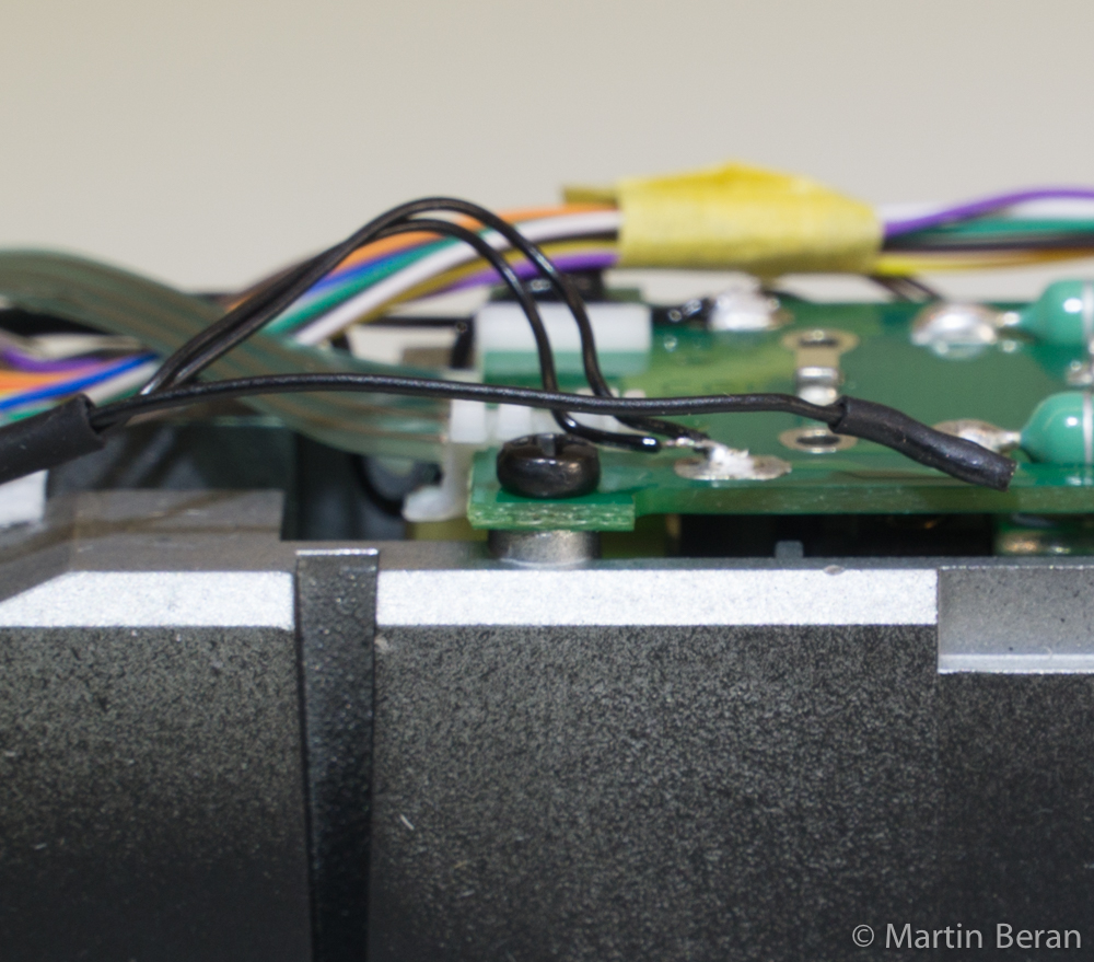 Actually the couplers offered by Roco feature four separate conductive paths but I need only two (DCC left and right “rail signals”). So I combined the strands into two pairs. Then all pick up wires from the two trucks got isolated and the leads from the couplers soldered to the now vacant pads at the pcb on the B end. Furthermore the unit received an ESU sound decoder. I used a generic one and uploaded the particular DB 185 sound file via the ESU LokProgrammer device (this might be stuff for another post). The process works really good- unfortunately only for ESU products. It is a good idea to do all the programming and fine tuning before the engine is converted to Dead Rail! Programming on the main (POM) is still possible over the air but I prefer the benefits bidirectional communication by means of a programming track.
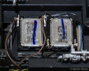 The Roco chassis provides enough space for the decoder. I made a little brace out of 0.5 mm styrene to support it above on one of the trucks. Last but not least two ZIMO “sugar cube” speakers found their new home in the battery compartment in the underbelly of the locomotive. As the ESU Loksound decoder is designed for a 4 Ohm speaker load, I put the two 8Ω “sugar cubes” in parallel. The result is quite delightful.
The Power Car
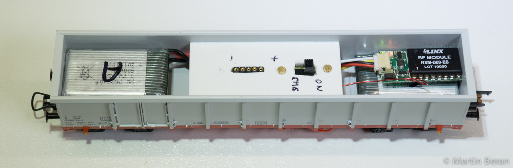
The power-car is were the real Dead Rail fun begins! It carries the batteries, receiver module, charging port as well as the on/off switch. For the power storage I chose to utilize three lithium-ion polymer (LiPo) cells @ 3,7V and 500mAh capacity each. The individual cells have a tiny safety circuit board integrated. Therefore overcharging and harmful low voltage conditions should be prevented. I bought the LiPo batteries at the local electronics store as well as all the other electrical components for this project. Whenever possible, I try to rely on local sources for the parts. For the car itself I choose another model made by Roco. It’s one of the very common Eaos series high side gondolas that roam the rails of Europe. In order to distribute the weight evenly the batteries got placed above the trucks with the receiver put atop of one cell. In the middle a piece of styrene mounts the switch and charging port and helps to establish a cleaner look by hiding the wiring beneath. The figure below shows how all the components are connected.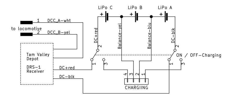 I also determined to reference the individual cells in alphabetical order as well as define a color scheme for the wiring. It worked well for this project so I will stick to it for the future. DC+ is red, DC- black. The balance leads for the LiPos (this is kind of a unique requirement for batteries assembled of multiples of those type of cells) AB – blue, BC – yellow, CD – green, DE -brown. Batteries with three cells provide 11.1V and this is a good match for our application. Therefore we have two balance wires in the colors blue and yellow. According to Tam Valley’s recommendations, 18.5V (5 LiPo cells) should not be exceeded. Finally the DCC leads from the DRS-1 module connect to the electrical coupler who matches its counterpart at the locomotive. The car provides enough space to arrange everything in a neat order. Sure, one could cram the parts in a smaller area but for the prototype I prefer to have some leeway.
Fill’er up!
Sooner or later every battery runs dead and needs to be recharged. For that purpose the cells can be taken out of the model or charged via a charging connector while staying in place. I opted for the latter. For this project standard IC style pin headers and sockets have been used. It works as long as not too much mechanical force is put onto the plug. But I might change to JST connectors in future Dead Rails installs. 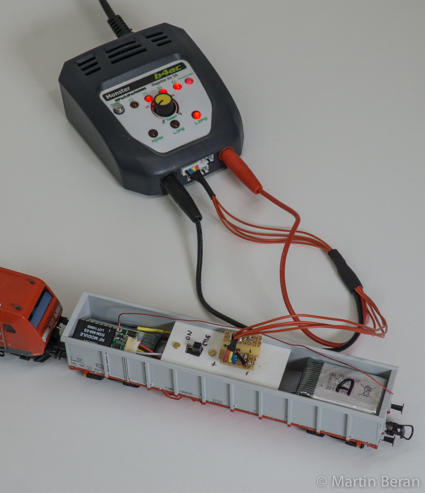 In order to prevent wrong polarity (not good for the battery!) I “keyed” the connector by offsetting the DC negative pin. In recent years, largely due to the advent of drones, the LiPo technology got widely adapted within the RC hobby community. So there is a wide range of suitable chargers available. For starters I picked a simpler unit that does the job for now although the displayed information about state of charge, voltage, etc. is limited.. Once there are more battery powered trains to be taken care of, a sopihisticeted charger might get acquired. Meanwhile a separate device showing the voltage levels of the whole battery pack as well as the individual cells is a handy tool everyone dealing with LiPos should have anyway.

Charging LiPo battery packs includes two major procedures. Frist there is the general charging of the storage device. This is done by means of a relatively “high” current fed into the mains of the battery (DC+ and DC-). Second the so-called “balancing” handles each cell individually in order to establish the same voltage (∼3,7V) for all cells in one pack. Balancing deploys very little current and therefore the leads can be way smaller than the main charging cables. As our Dead Rails trains feature pretty small batteries compared to high performance power packs e.g. used in model aircraft, relatively thin wire can be used for the main leads as well. This also reduces the mechanical force on the plug. So far I have good results with my customized charring cable. I only had flexible wire in red available so I used colored shrink tube to establish the color code of the individual wires.
Operation
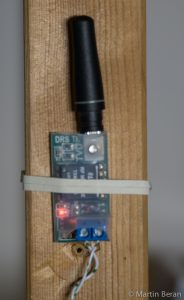
After all the fiddling it was time to run the first train- finally! 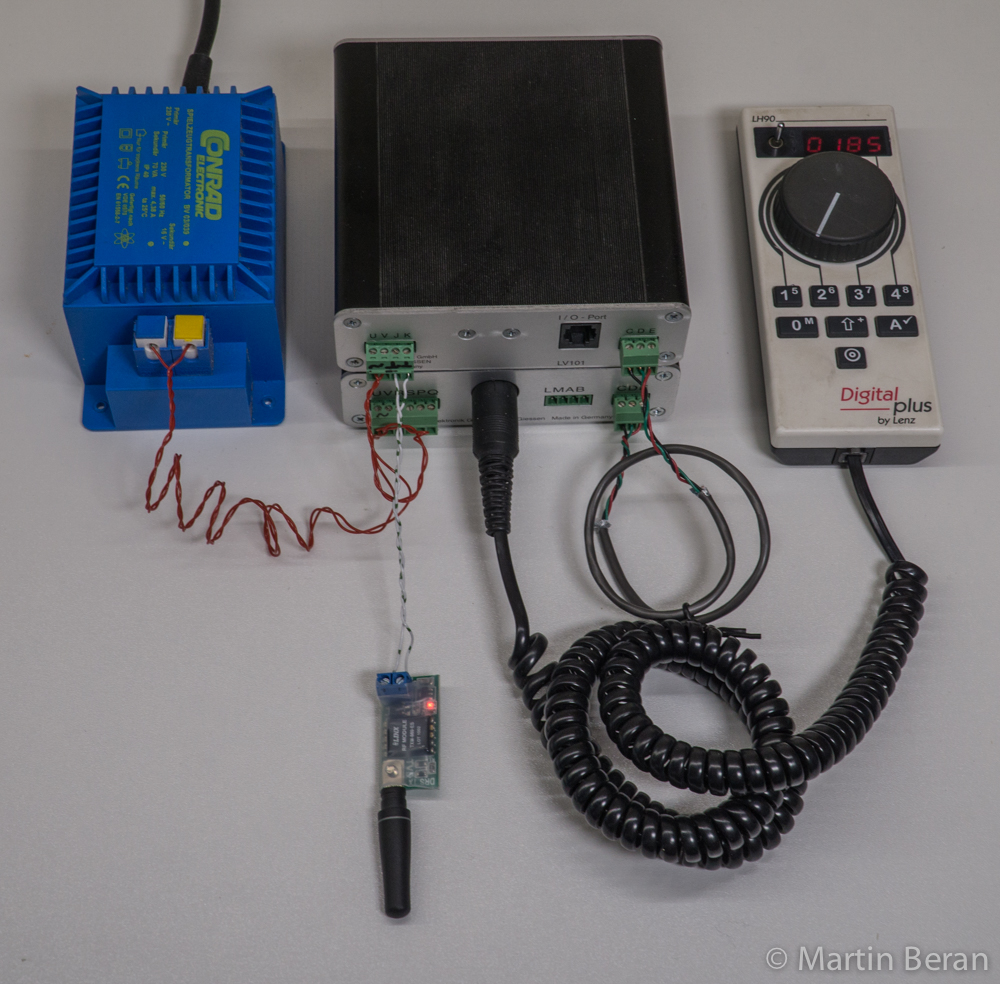 The Tam Valley Depot sender module got connected to the track output of my DCC system (Lenz), followed by coupling the locomotive to the power car. The consist had its maiden run on a circuit of Roco-Line “high-end” set track on the floor. As soon as the DCC system is turned on and the switch in the power car is flipped in the ON position, two LEDs light up on the DRS-1 receiver board. The green light indicates that there is sufficient power available and the red one gives an idea about the radio signal strength. This is especially helpful for setting up the perfect radio configuration, namely the location of the sender as well as the orientation of the receiver antenna.
As the test track runs through three rooms of my apartment it was a little bit tricky to find the perfect location for the sender but in the end I managed to get decent reception throughout the circuit. I will obtain more sender modules from Tam Valley in order to improve radio transmission across the apartment as I plan on laying more temporary track all across. There might be a separate post about my “Teppichbahning” – German for “carpet model railroading” ambitions one day. For testing purposes I had the test train running with all the sound and lights on for more than an hour at a steady pace. There was no noticeable decrease in speed or pulling power. Time will give more data on performance but for now it seems that the setup provides enough running time for typical operation sessions.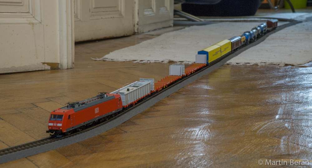
Lessons Learned
I started this project to get first hand experience with battery powered trains and radio controlled operation. I did so partly out of curiosity but also in order to determine if I want to further pursue into this field in the future. Here are some takeaways and findings:
- Battery powered operation can be a viable alternative to conventional layout wiring but it might take a while till this approach will become mainstream – eventually. Start small and evaluate if this is the right thing for you and the goals you want to achieve in your railroad modeling!
- Dead Rail technology requires technical skills, the willingness to tinker and considerable resources to get up and running. It’s definitely not a “ready to run & comes for free” feature.
- On the other hand Dead Rails is a step closer to run trains in prototypical fashion as the power is carried on the trains (this argument might be somehow off for trams and heavy electrics). Furthermore with the challenges comes the satisfaction once the train is on its way without any power on the track!
- Feed and care of high power density batteries is an interesting but also serious field of activity. Common sense and caution do the trick. In (indoor) model railroading overall energy levels are lower than in high performance applications like model airplanes so extrem hazardous situations are unlikely to appear. But mind the risks and be attentive!
- There is no standard for Dead Rails radio communication etc. established yet and probably wont be in the foreseeable future. Several manufactures offer their proprietary systems and once a decision has been made for a particular technology it is difficult (if not impossible) to change or rely on a second source should the need arise.
- Keep your goals manageable! I think it is way to ambitious trying to get all the parts needed in a tiny critter at the first time. Too many unknowns multiply the chance for failure! Sure, omitting the power car would be slicker but the actual arrangement works well, provided valuable know how for upcoming projects and- last but not least, lots excitement and gratification. Furthermore, due to the minimal alternations of the locomotive, it would be easy to undo the changes if it is decided that Dead Rail is not the way to proceed (for now).
- Start the conversion to Dead Rails with a perfectly working locomotive! That includes all decoder parameters configured. Simple changes can be done via POM or even via the programming track with some twists but due to the one-way radio communication path its hard to determine if the CV changes took place eventually.
- Be aware of the slightly different radio standards! Physics is the same all over the world but jurisdiction is not. Signal strength is very limited so it is unlikely to disturb your neighbors though. Suppliers usually offer their products set up for particular regions which is good for staying on the “right side of the track” in FCC regards but watch out to get the right modules as there is no mix- just match!
Conclusion
Dead Rail could develop into “the new thing” in model railroading. Meanwhile it is still in it’s infancy and offers a while field of experimenting. I am happy with the results and will carry on with locomotive conversions as well as power car designs. Main applications will be my “Teppichbahning” – temporary layout on the floor as well as the little On30 layout which is in the planning stage right now. Both projects benefit from the advantages Dead Rail technology has to offer. I will keep you posted!
Links and recomended reading
Battery Power without compromises – Model Rail Roader Magazine, June 2016
Running trains with batteries & radio control – Model Rail Roader Magazine, May 2015 (article can be found on the Dead Rails how-to page)
Battery Powered Models in H0 Scale – Model Railroad Hobbies Magazine, November 2014
Tam Valley Dead Rail Information there you can find a version of the very helpful DCC Dead Rail e-book