
A DIY signal generator
After having a lot of fun building the digital oscilloscope from a kit I decided to tackle a signal generator kit next . This makes a perfect match for the scope and will be useful checking circuitry. The design is centered around a “classic” ATMEGA16 μC paired with a common OpAmp to boost the signal and a two line LCD with some push buttons as user interface. Somehow this reminds me of a typical project for student at a technical college and the whole thing probably grew out of such an undertaking.
What’s in the box?
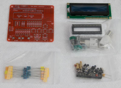
I ordered a DDS function generator kit from trade_spotting in China via Ebay. Cost was about $14.- with shipping. It took nine days till I had it in the mail- not bad at all! In the box, or better envelope- come the PCB, the LCD board as well as three bags with resistors, capacitors, small parts as well as the bnc connectors, potis plus- last but not least the ICs with sockets. That is it- no manual or assembly instructions are included. Well, as it is a pretty simple kit and all values are clearly marked on the board it is not really necessary to have guidelines. The good news is that this is a common design and there are some websites out there that provide some information but it definitely helps if one has some experience in putting electronic circuits together.
Putting it all together
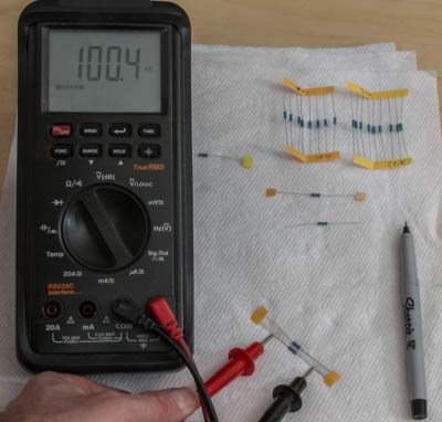
First order of business is the get familiar with the parts provided. Are there any missing items and what are those restore values in particular? I check all components for their values and mark them if needed. After that it is all about soldering the parts in place. I usually start with the resistors, paying attention not to mess up the values. Capacitors and the quartz are next followed by the IC sockets, push buttons as well as the pin headers for the LCD sub board.Once the “flat” components are in place, we turn our attention to the “bigger” parts like the BNC-connectors and potentiometers.
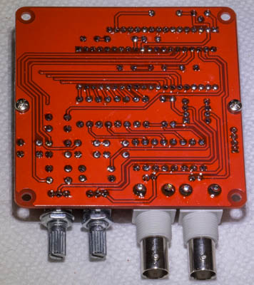
Soldering goes well on this board. The surface did not receive any special treatment and it seems that the pads are big enough to provide enough “meat” for a proper soldering joint. All in all this one is a going together a little bit easier than the oscilloscope kit. So well, after about 1 1/2 hrs the all the components are tacked in place. As always, patience, light- lots of light!! and a good soldering iron pays off. After test fitting the LCD is comes off again in order to insert the ICs later on, once power has been connected to the device.
Power it up!
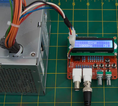
As straight forward as those kits are, providing power to the devices is up to the owner/user. In this particular case we need +5V (for the ICs), +/- 12V for the OpAmp to generate the signal and, of course- Ground. None of the voltages are generated or controlled on the board. So I turned to a ATX power supply from a retired PC (thanks Brian!) as a power plant. PC power supplies are great source of power. They offer multiple voltage levels and lots of amperage. I think the one I have in use easily could run several dozens of DSS. All the funny colored wires coming out of the unit have a meaning- in this case red stands for 5V+ , white for 12V+ (according to the ATX standard it should be yellow), blue gives us 12V- and black is Ground. Don’t forget to connect the green wire with Ground to start the whole device up! On day (read “never”) there will be a switch in order to more conveniently turn the power on and off. Some sort of plug connection is useful so I opted for a four pin Molex connector. It makes sense to omit the pin header provided with the kit and solder the power wires for the connector right away. Desoldering firmly placed pin headers is not fun- please do not ask me how I know this…
Get it going!
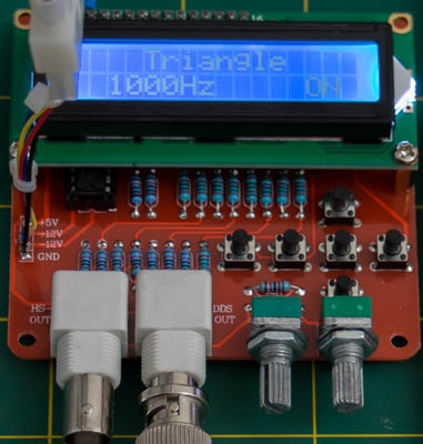
Once we established a connection to the power supply we check the voltages on the IC sockets. If we are satisfied with the readings at the particular positions (check ATMEGA16 pinouts), disconnect the power supply and put the ICs in place. Just make sure all pins hit their particular hole! There is almost nothing better than feeling an IC sliding in position with all pins in correct order- well, at least for a geek like me. Once everything is ready to go, connect the generator output (DDS-OUT) to an oscilloscope and power it up. If you encounter an blue screen but nothing more- don’t panic! Just turn the little trimmer “north” of the LCD in order to adjust contrast of the display. The push buttons provide a basic but easy to comprehend user interface for modes (the ECG setting is kind of cool) and frequency. -The center button toggles the actual setting to ON. Make sure the display shows ON in order to read the signal at the port! The two dials up front offer offset and amplitude variations.
Conclusion:
The DDS signal generator is a nice kit with great value! It goes together easy and smooth. The offered value is pretty awesome and this litte device can be a good gadget in your toolbox (if put in a case) or on the workbench. Providing power with multiple voltage levels might be a challenge, especially if you plan operating on batteries.